Case Study: Replacing the Video Card of a Dell Inspiron E1705 (9400)

Following case study is provided by notebookcheck.pl, our Polish editor team.
One of the most frequently asked questions about laptops is: What is required to replace a notebook's video card? Well, it depends. In general, it is not possible at all.
This is a major difference to desktop computers. Even dedicated GPUs are usually soldered to the main board. However, there are some exceptions, e.g., Dell notebooks. Detailed information about upgrading or replacing a notebook's video card can be found here.
Andi, a Dell Inspiron E1705 (9400) user, demonstrated how to replace the GPU of his Dell notebook and provided us with a description of the whole process. Thanks Andi! Following is his description.
First of all we are obliged to warn the Reader, that all attempts to disassemble a notebook result in loosing guarantee rights and are, therefore, performed at own risk and responsibility.
Originally, my notebook, a Dell Inspiron E1705 (9400), was equipped with a NVIDIA GeForce Go 7800 video card. In order to improve its graphical performance, I decided to replace it by a NVIDIA Geforce Go 7900 GTX.
Attention: In the end (see below) it turned out, that the Geforce Go 7900 GTX needs more space than the Geforce Go 7800, because it is equipped with two heat pipes, while the Geforce Go 7800 has only one. Therefore, I needed to use a pair of side cutting pliers to cut out two pieces of the inner part of the case.
Please, make sure that you have an electro-static discharge protection, screwdrivers, a pair of side cutting pliers, and compressed air at your hand before you start.
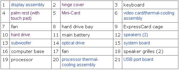
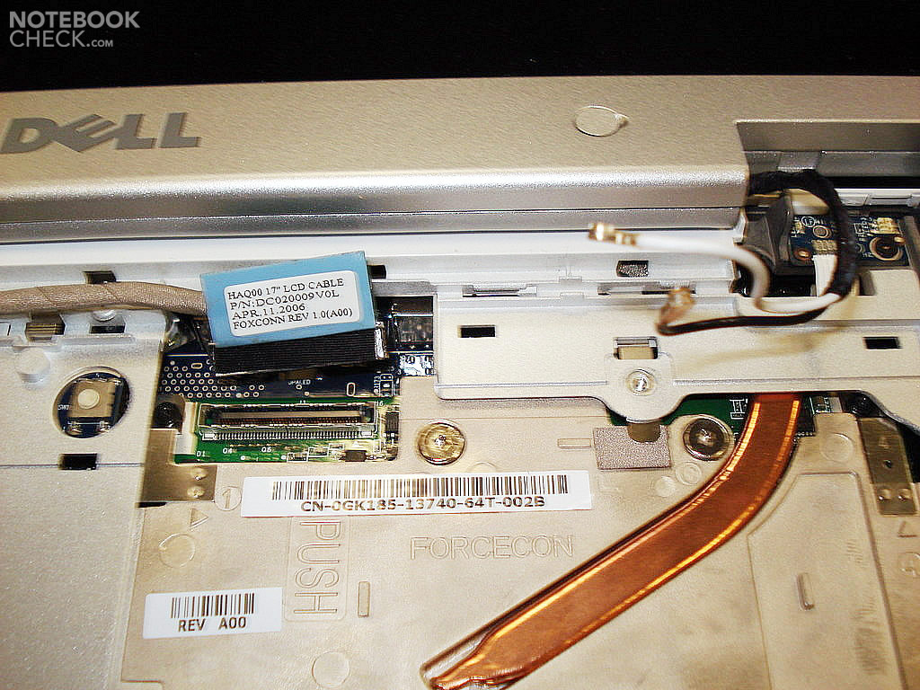
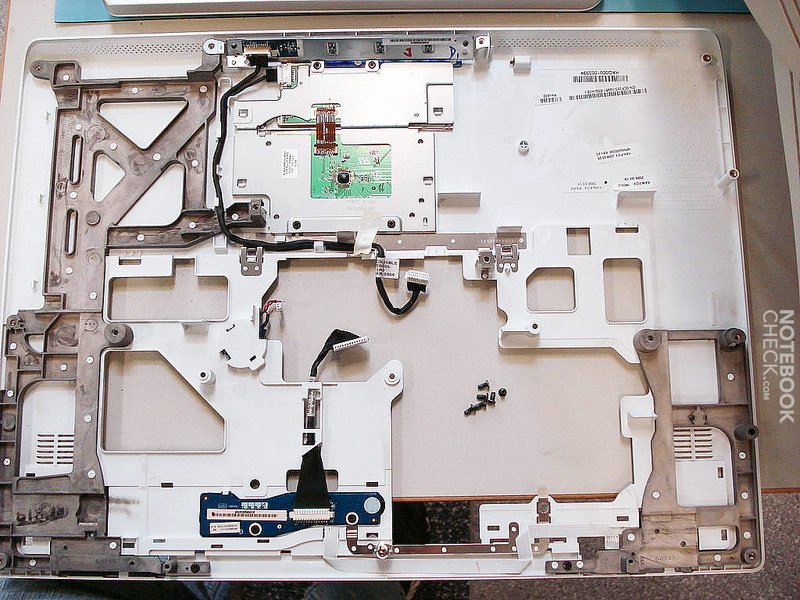
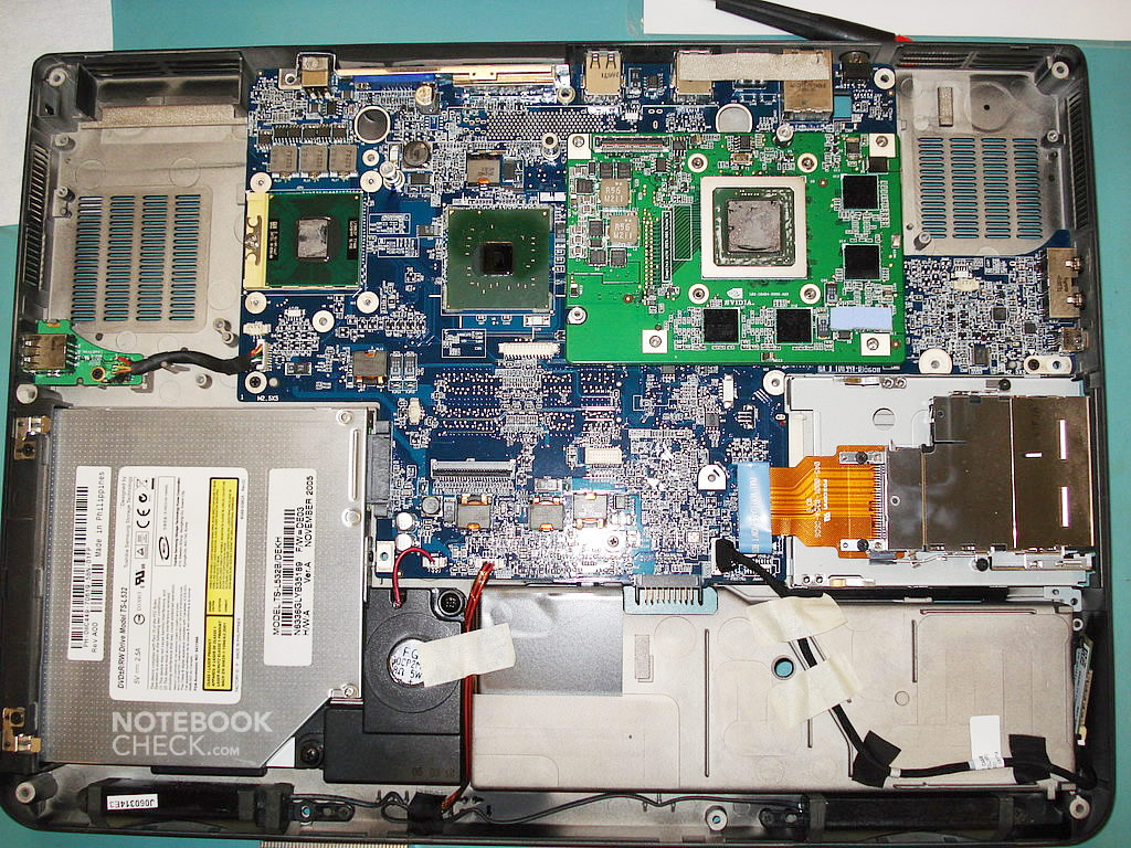
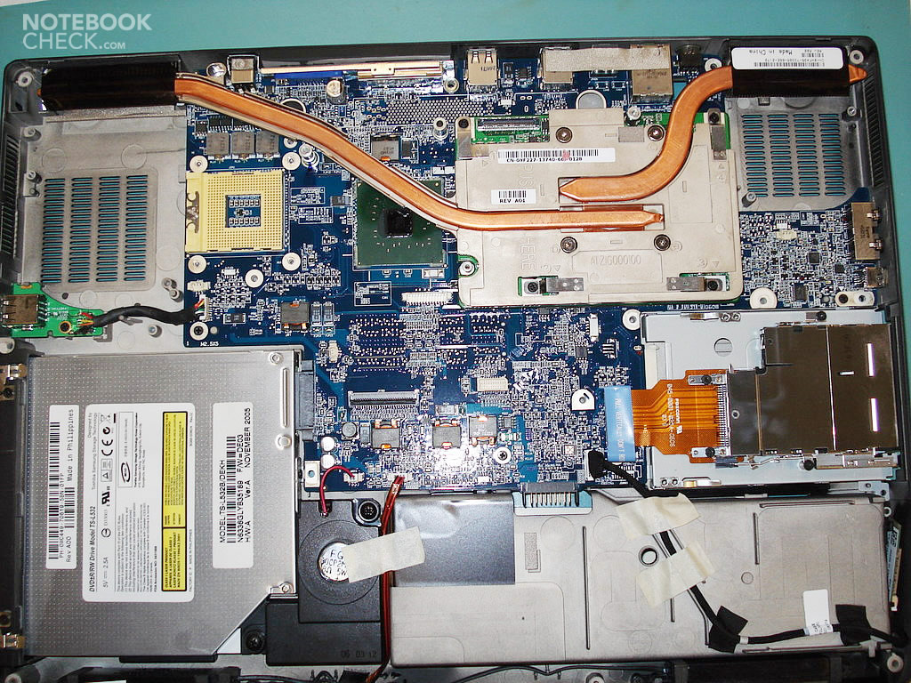
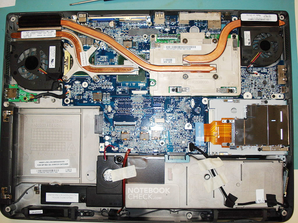
First of all, let me show you how the notebook is built and describe the parts:

Before getting to work, the key issue is the appropriate ESD (Electro-Static Discharge) protection. It was highly important for me, because this way you can avoid damaging the fragile components of the notebook.
So, I put on proper gloves and antistatic armbands, and worked on top of a grounded anti-static pad.
Before starting the manipulations inside the laptop, the battery and the integrated hard disk had to be removed. Furthermore, the WLAN card must also be removed, because otherwise there is no way to dismantle the screen. Unfortunately the Dell E1705 is designed in a way which makes it hard doing anything without disassembling the display. It is yet a long way to be able to access it...

Removing the hard disk (Dell's official manual):
http://support.euro.dell.com/support/edocs/systems/ins9400/en/sm/hddrive.htm#wp1123687
Removing the WLAN card (Dell's official manual):
http://support.euro.dell.com/support/edocs/systems/ins9400/en/sm/cards.htm#wp1009645
In our case one has to disconnect pins No.1 and No.2.
Please remember, that you have to connect the white cable to pin No. 1, and the black one to pin No.2.
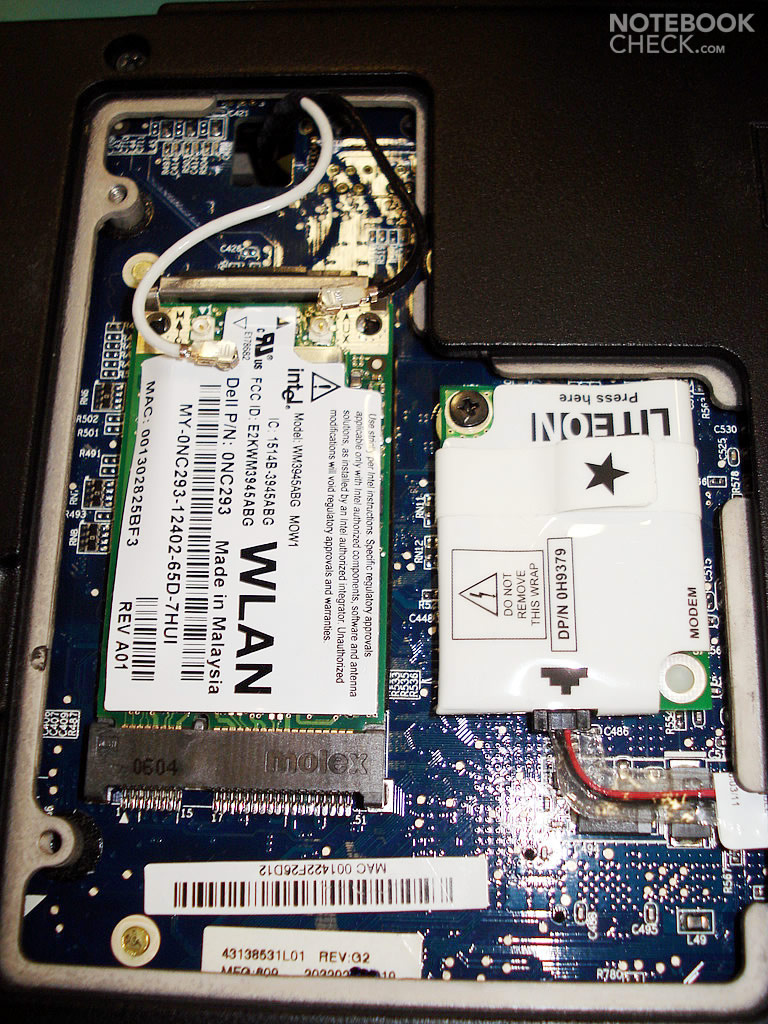

The result looks like on the photo below. One has to carefully lead both antenna cables of the WLAN card to the notebook's top side. While disconnecting the joints, one has to apply some force, as they're attached tightly. Be careful not to pull the whole thing out of the printed circuit board (PCB).

The next step is to unscrew the laptop. We start with the cover containing the power switch and the indicator lights (the hinge cover).
The following link to the Dell's website will be useful here:
http://support.euro.dell.com/support/edocs/systems/ins9400/en/sm/hingecvr.htm#wp1123881
Let's continue at the right side (there is enough room for a screwdriver). Be careful not to damage the lacquer of the case (it's recommended to put a piece of paper beneath the blade of the screwdriver).
Next, bending the sides of the cover, try to gradually pull it upwards.
It is attached to the rest of the case very tightly by some clasps and bolts. You shouldn't pull at the right part of the cover while trying to remove it, because you could probably break it in half that way. (there is a printed circuit board with the power switch, multimedia buttons and indicator lights underneath).
After removing the hinge cover, you'll get the following result:
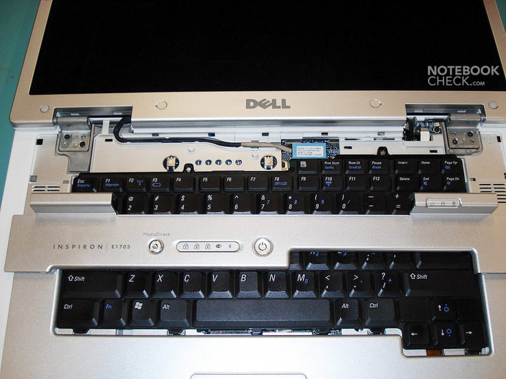
Now the keyboard has to be disassembled. It is affixed at its upper part by two screws. After unscrewing them, you put the upper part of the keyboard upwards and then pull it out in the direction of the screen. You can put it (turned upside down) on the touchpad.
Further details about dismantling the keyboard can be found at Dell's website:
http://support.euro.dell.com/support/edocs/systems/ins9400/en/sm/keyboard.htm#wp1111863
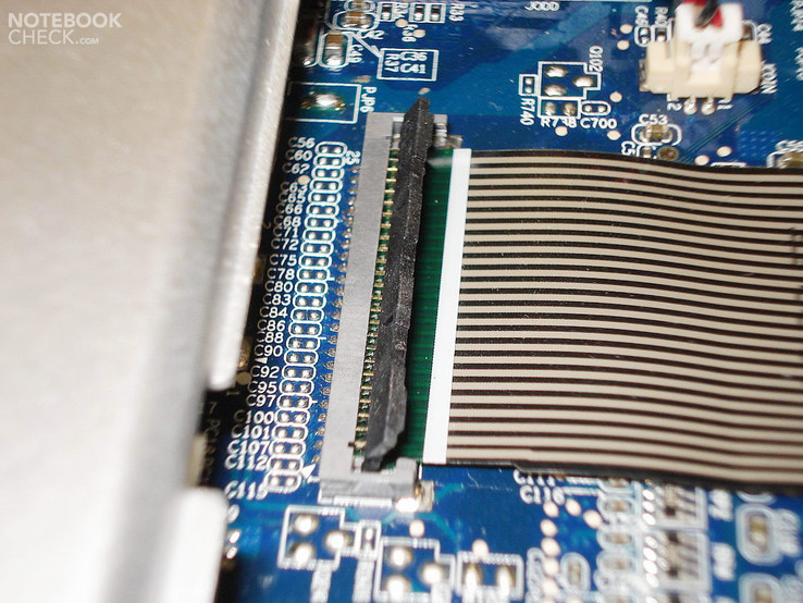
Disconnect the keyboard connector by lifting the black cover at the ribbon cable's side. Do not pull the grey joint, as it is soldered to the printed circuit board (PCB).
After removing the keyboard and rearranging the WLan cables, it's time to separate the LCD panel:
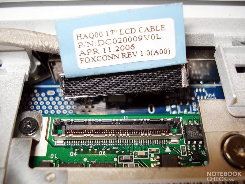
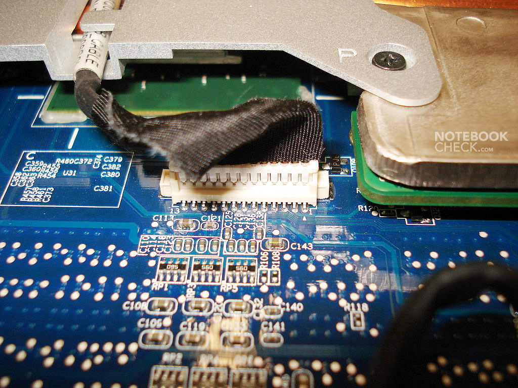
It is connected to the slot on the video card by a 30-pin connector.
In order to disconnect it, one has to grasp the blue tape and pull the connector upwards.
Here you can read about disconnecting the LCD panel (manual from the Dell's website):
http://support.euro.dell.com/support/edocs/systems/ins9400/en/sm/display.htm#wp1006390
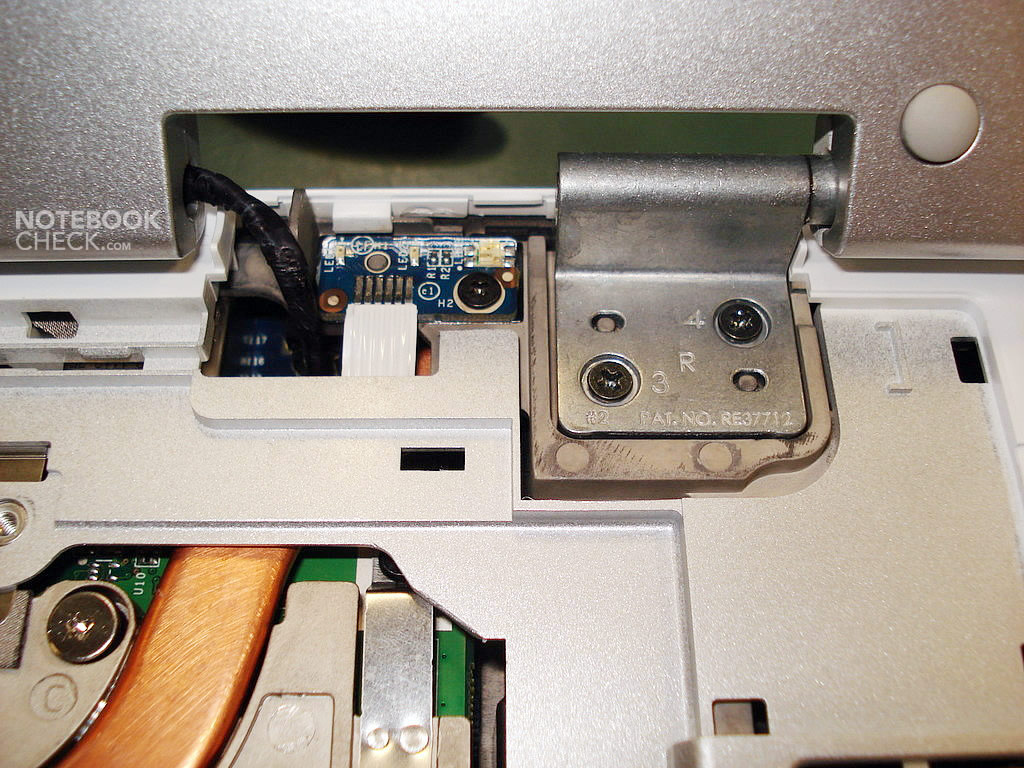
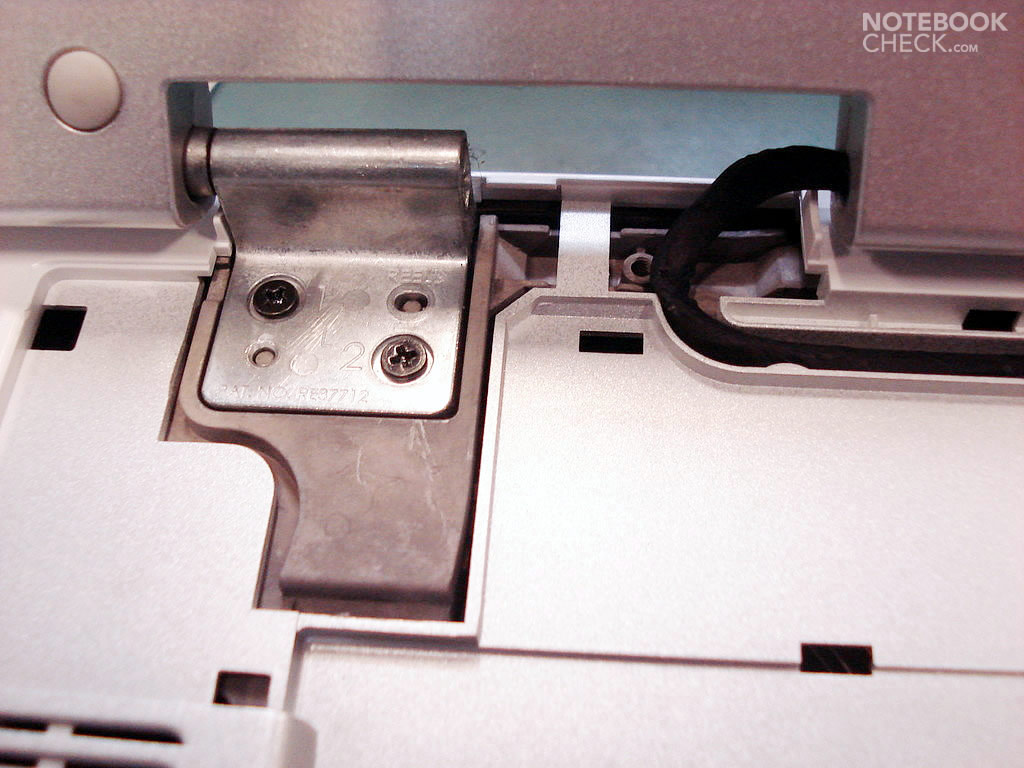
We've almost got rid of the LCD screen – you'll only need to unscrew another four screws which fasten it to the case. The left hinge has a small extension, which fits into the case. Hence, it's recommended that after removing the screws you should lift the hinges a little, pulling them away from the case, and then pull them out behind the laptop. If everything went well, you should hold the LCD panel with the projecting cable leading to the video card and two cables of the WLan card. During the following steps you won't need them anymore.
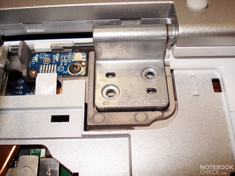
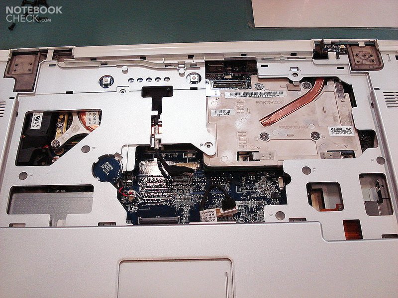
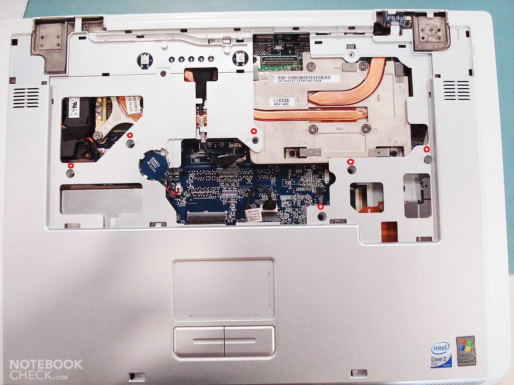
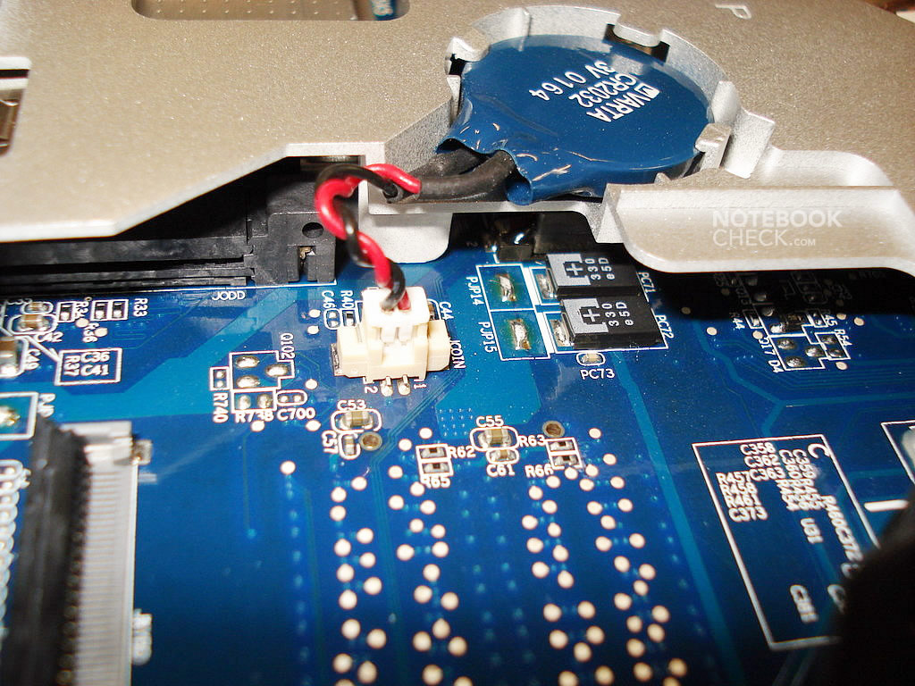
Now, you should disconnect three connectors of the motherboard (see the last picture): the one belonging to the BIOS battery, the one of the power switch and the indicator lights, and the one of the touchpad. All those parts are fixed to the top case of the base unit, which you need to remove next.
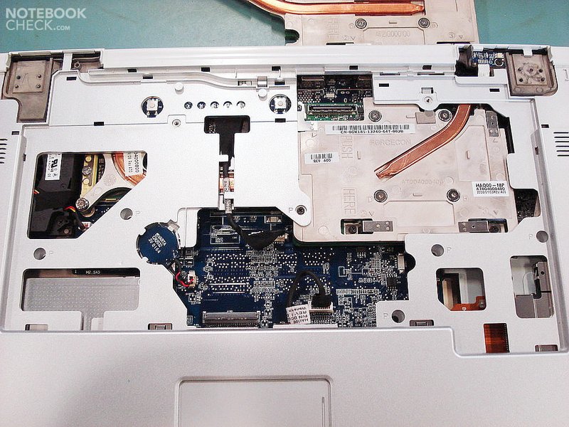
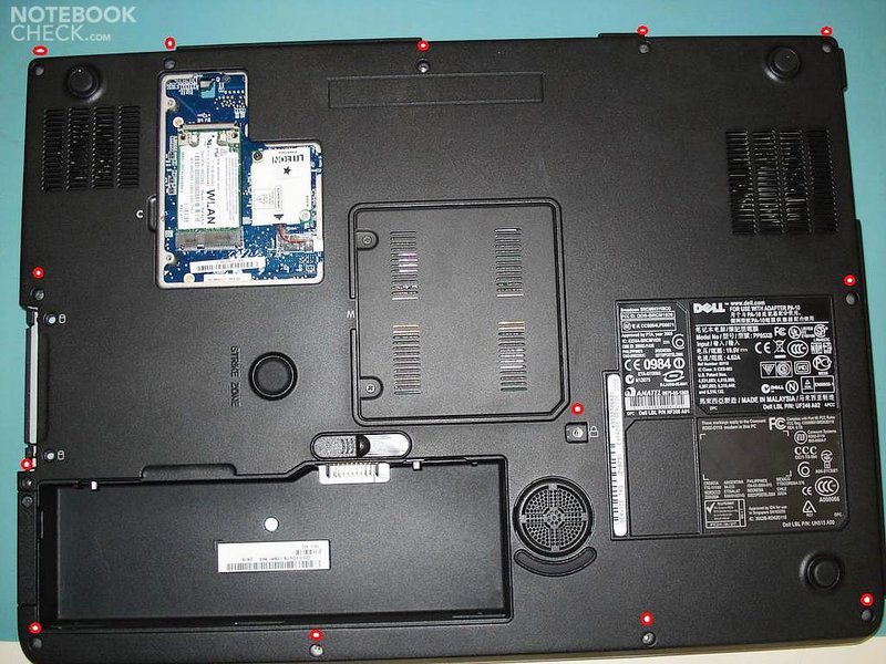
Unscrew the screws starting at the upside of the base unit (marked with small red circles) and those at the bottom of the base unit. Then remove the top case carefully and put it to the side. You can wipe it clean or clean it with compressed air.
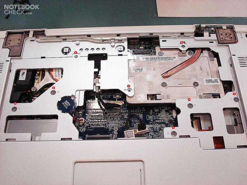
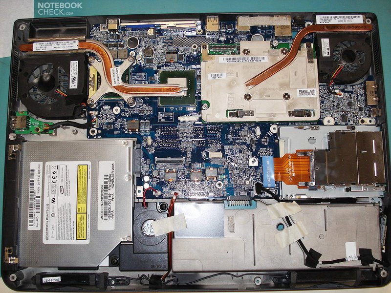
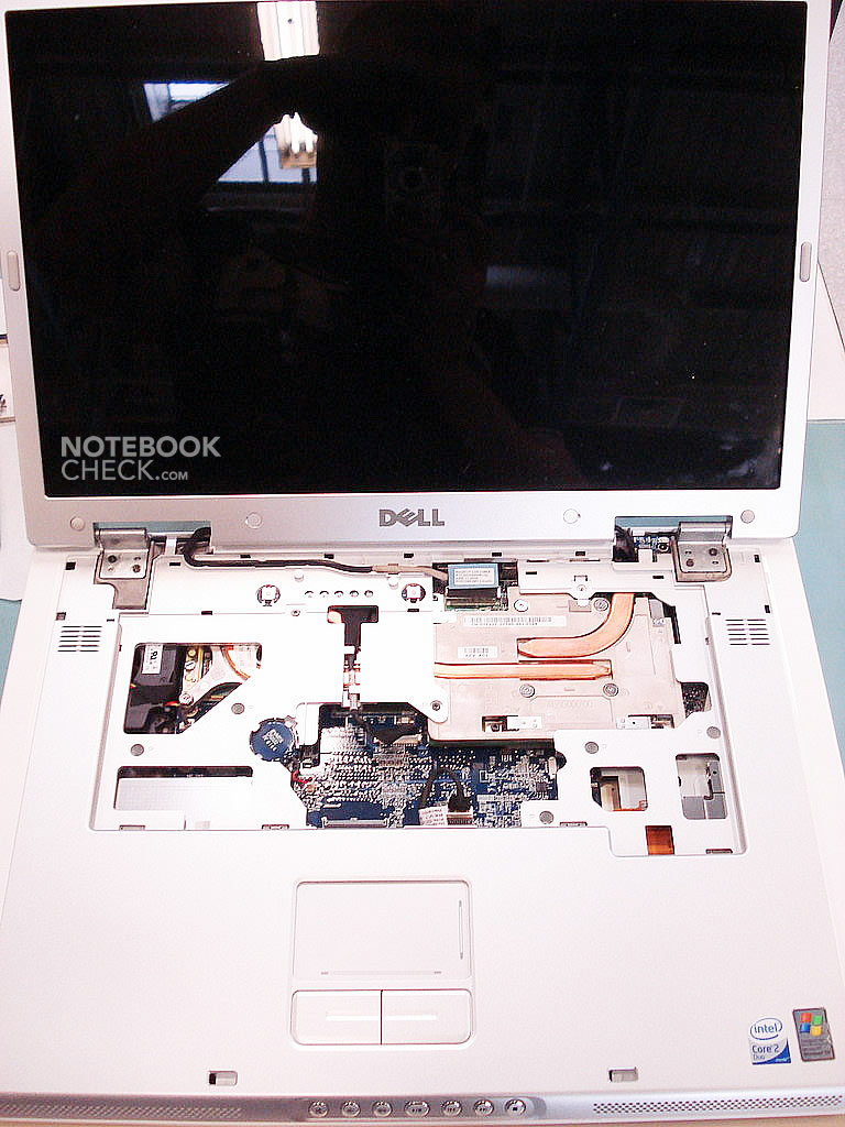
Finally, you're now inside and can disassemble everything you wish.
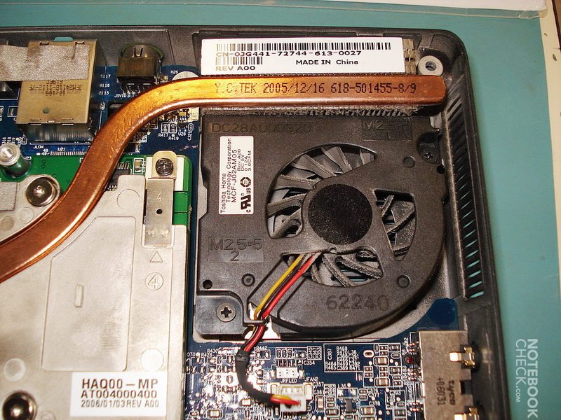
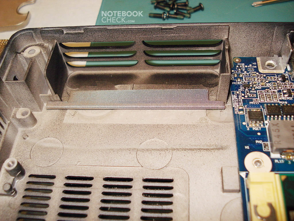
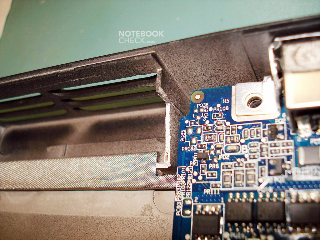
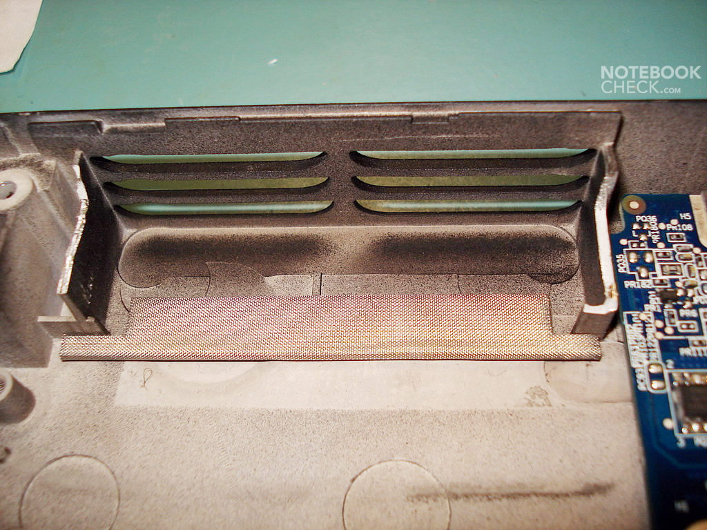
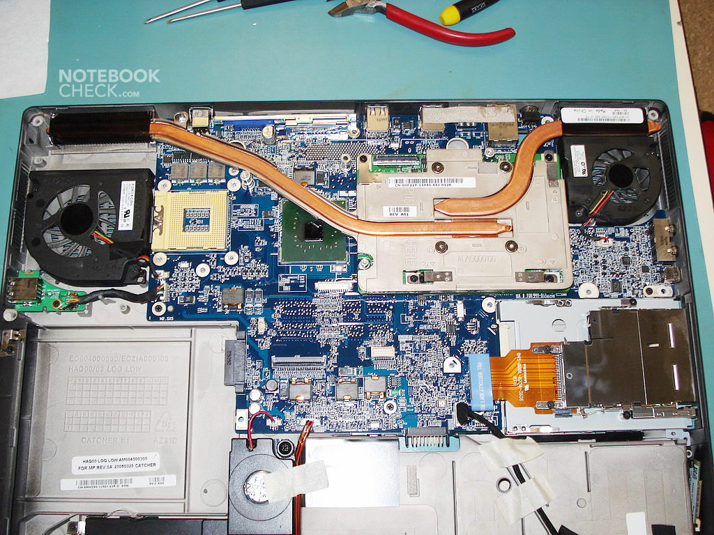
Let's start by cleaning both fans. Unfortunately, there is no immediate access to them, so every time you'd like to clean them, you have to take the laptop into pieces. In my view, this is a big drawback of this notebook.
Let me one more time refer to the manufacturer's website:
http://support.euro.dell.com/support/edocs/systems/ins9400/en/sm/fans.htm#wp1000550
In order to dismantle both fans, you have to disconnect the connectors from the motherboard and unscrew two screws, which fix them to the case (see photos below).


When we've got so far, maybe it's time (optionally) to disassemble the cooling of the CPU and exchange the processor itself.
First, take a look at the following links:
http://support.euro.dell.com/support/edocs/systems/ins9400/en/sm/cpucool.htm#wp1000001
http://support.euro.dell.com/support/edocs/systems/ins9400/en/sm/cpu.htm#wp1084976
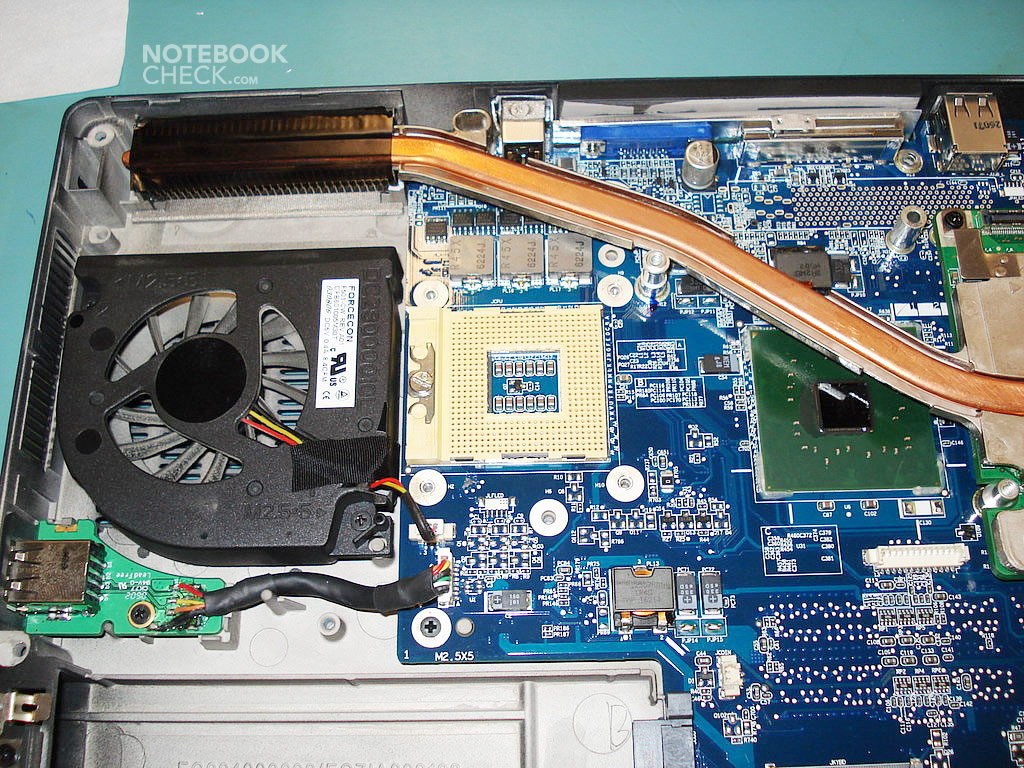
In order do dismantle the CPU's cooler, unscrew four screws. There are no more surprises awaiting you here, the whole thing comes off easily. Before removing the CPU, one needs to twist the screw on the Socket 479 clockwise with a screwdriver. Correspondingly, after replacing it with a new unit, you should twist the screw to the left, until you hear a distinguishable click. Because of the pins' arrangement, the CPU can be placed only in one way onto the socket. So, you shouldn't apply too much force. On the socket itself there are signs showing the direction in which one should turn the screwdriver in order to remove or replace the CPU. Those are: an open (to the right) and a closed padlock (on the left side of Socket 479) symbol.
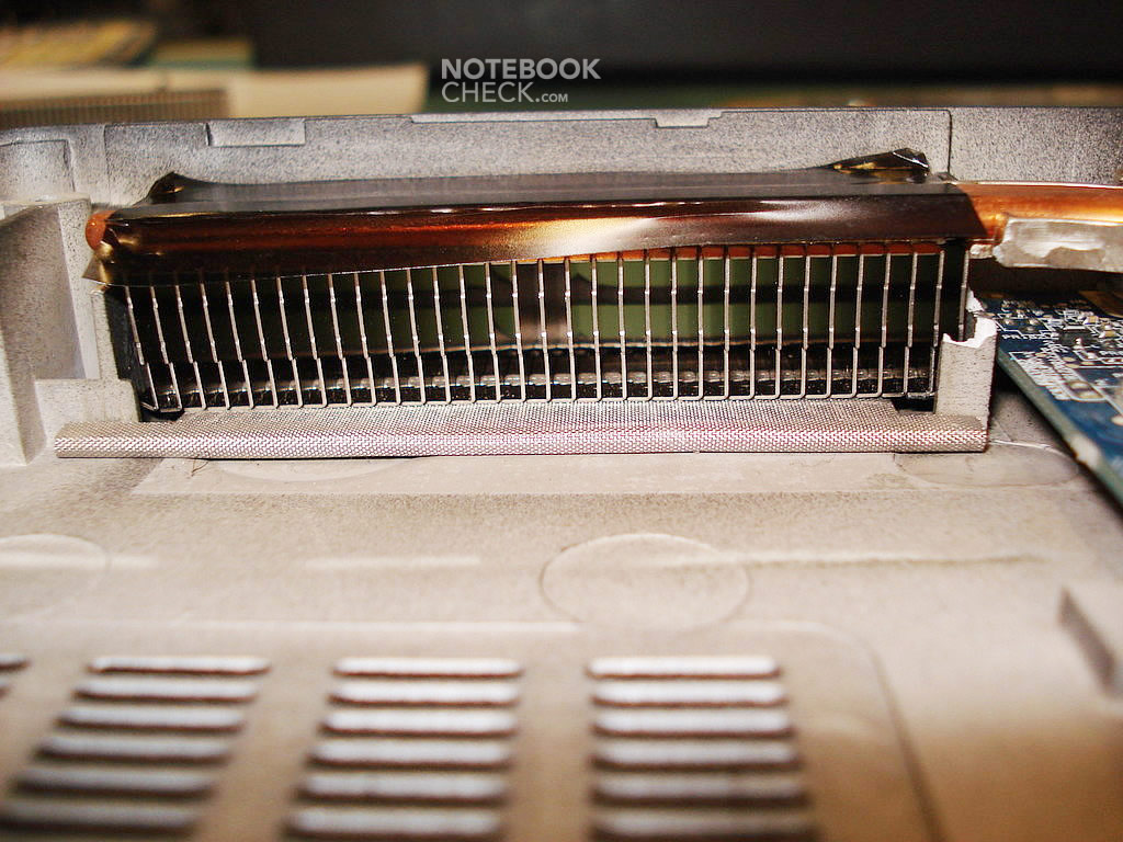
The cooling system itself can be cleaned with compressed air.
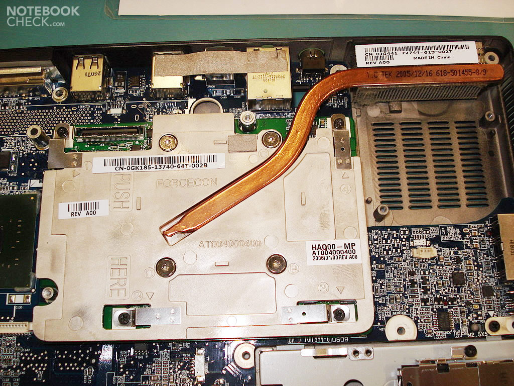
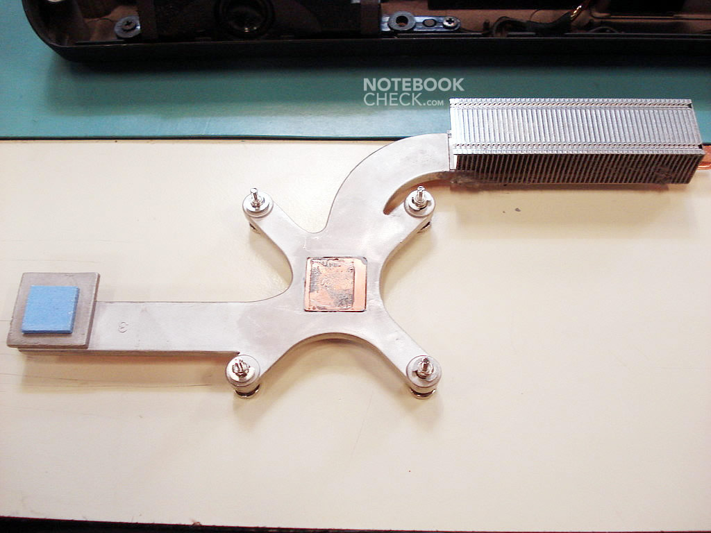
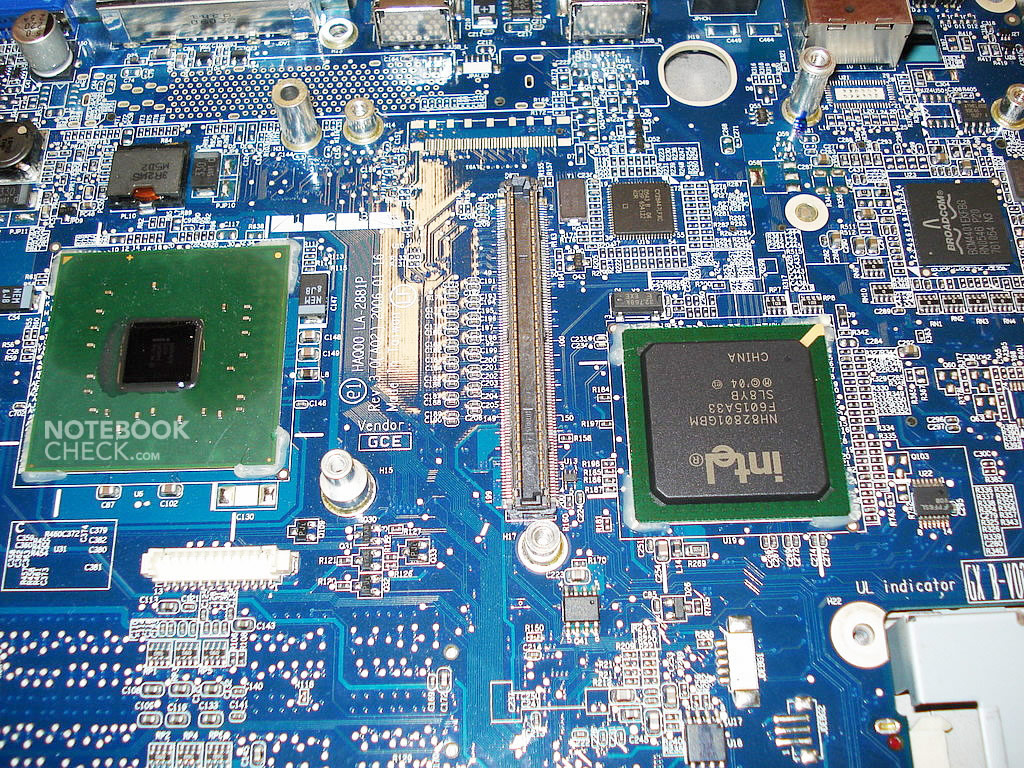
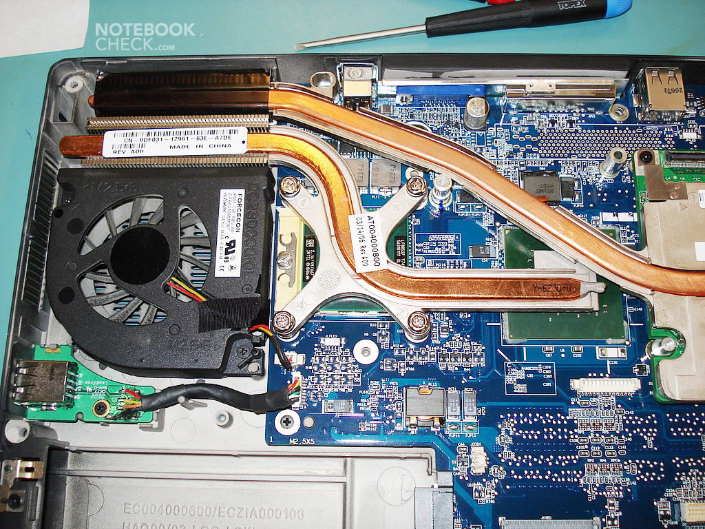
Next the video card's cooler has to be dismantled.
Dismantling the video card (manual from the Dell's website):
http://support.euro.dell.com/support/edocs/systems/ins9400/en/sm/video.htm#wp1006368
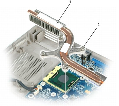
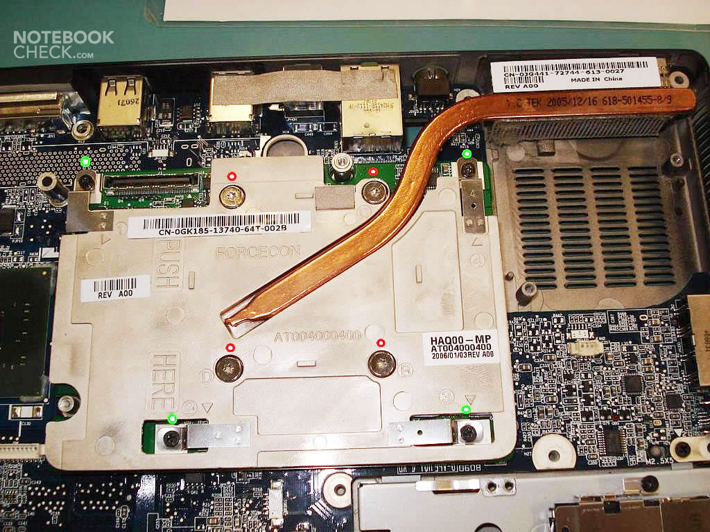
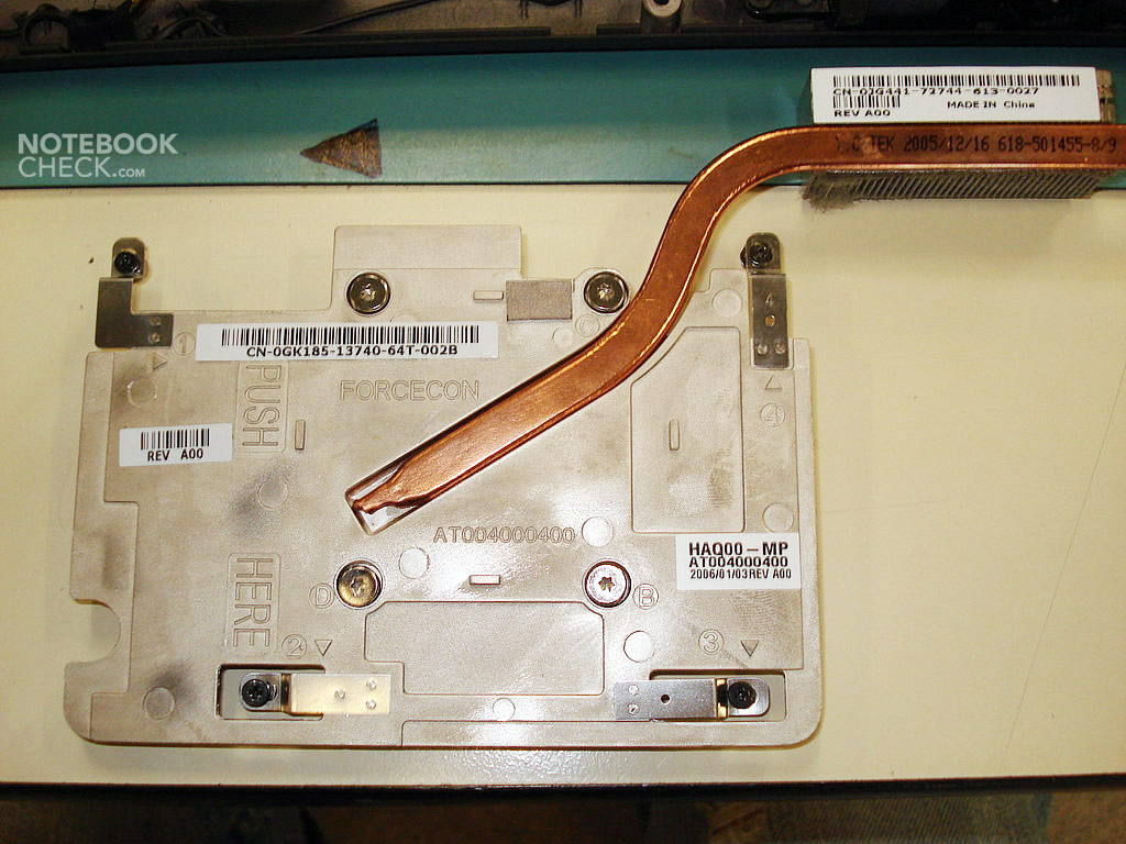
In order to only remove the cooler and apply a new cooling paste you need to unscrew just four large screws placed in the center of the radiator (marked with red circles on the first photo). This shouldn't cause any serious problems.

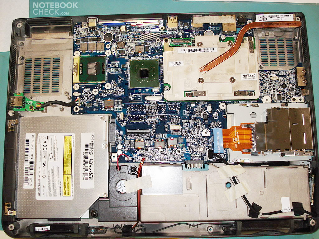
Now you can get on by removing the video card from its socket (it doesn't matter if you remove it with or without the cooler). If you do not want to disassemble the card, and would only like to exchange the thermal paste, it is enough to unscrew four large screws affixing the radiator itself.
However, if you want to replace the video card, you have to remove some more screws placed around the cooler. Actually, you have to unscrew all the remaining ones (marked with green circles in the picture).
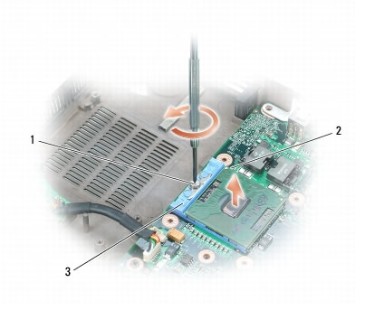
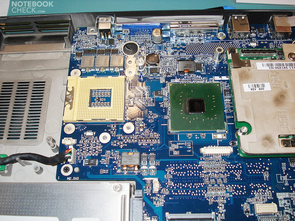
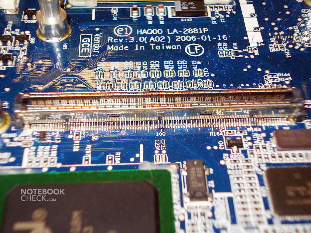
When you've managed to get rid of all the screws, it's time to remove the card. In this very moment I hesitated a bit, but since everything went smoothly up to this point...
Important note: the PCI Express card slot is placed on the left side of the video card, so you should grasp the card in this area and gently pull it up. You shouldn't pull the Express card out, as you can damage the connection on the motherboard that way. Try to remove the video card by holding it perfectly horizontal.
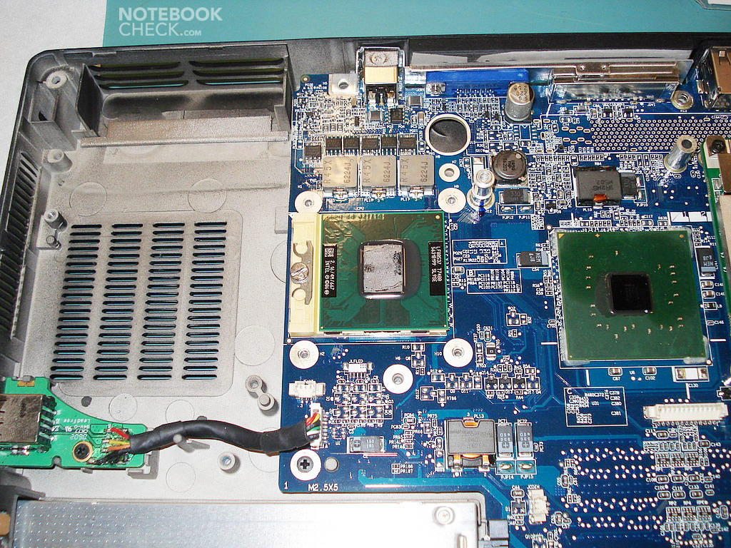
The final result looks like this:
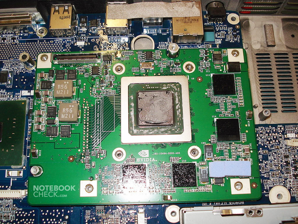
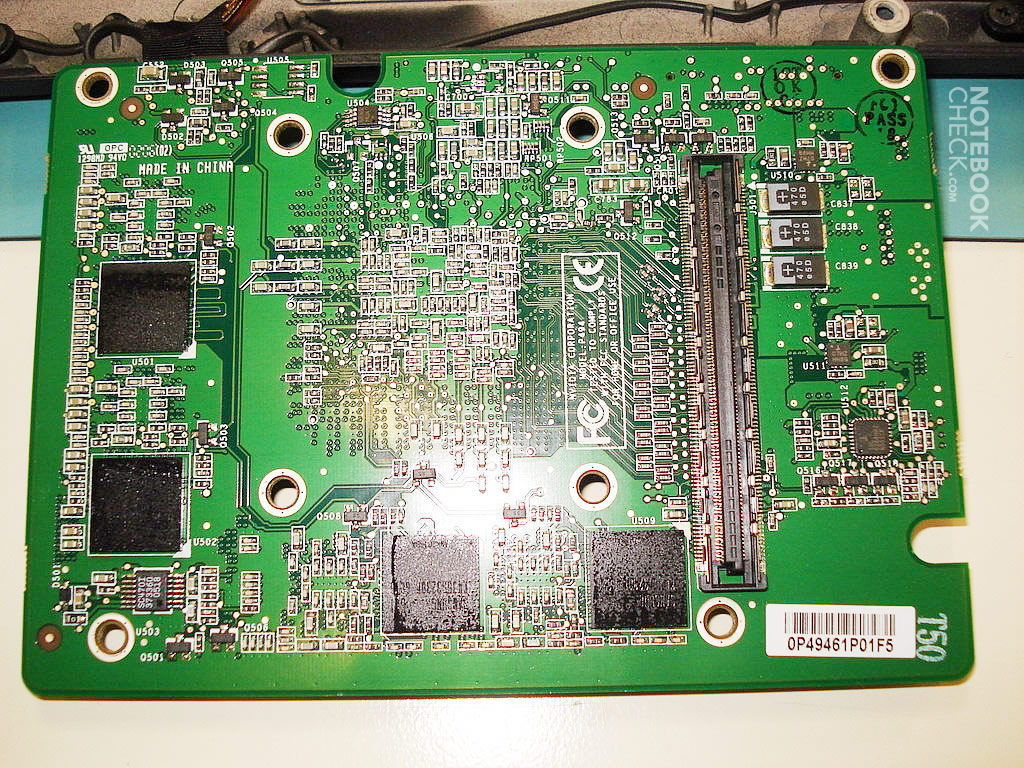

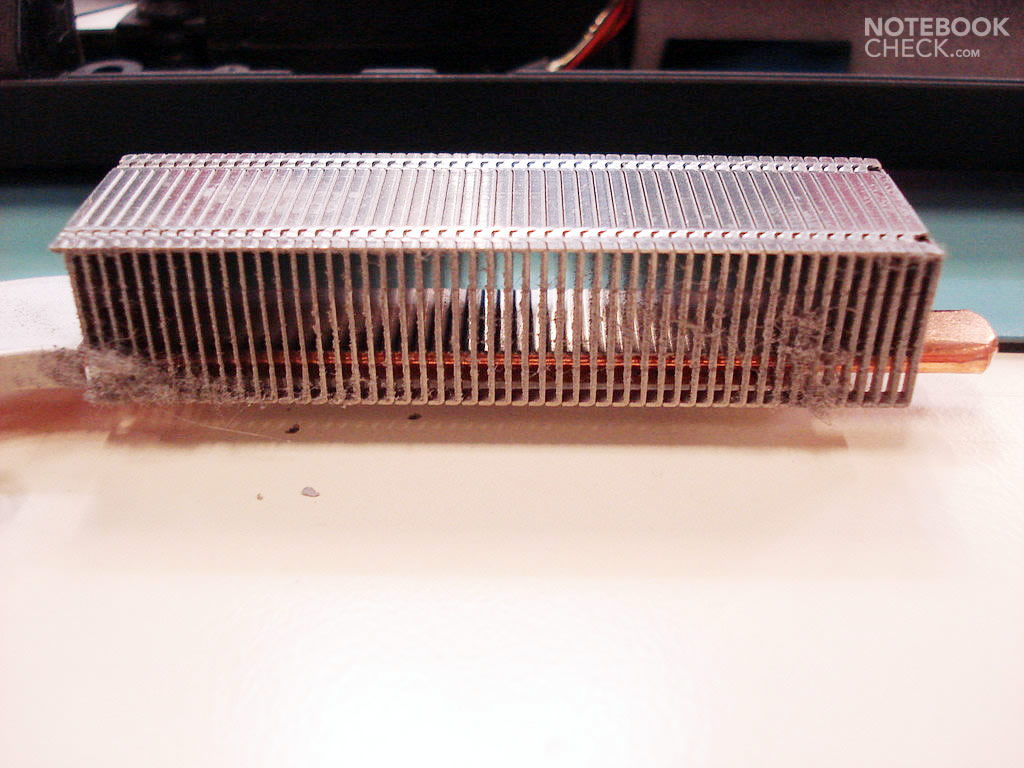
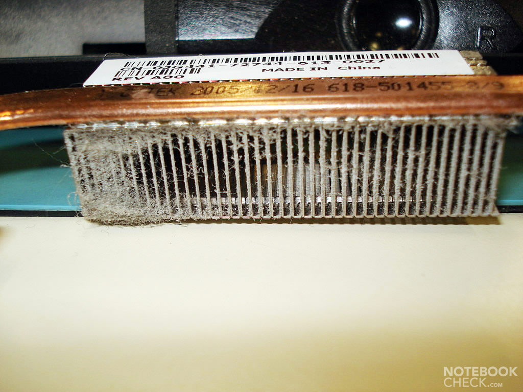
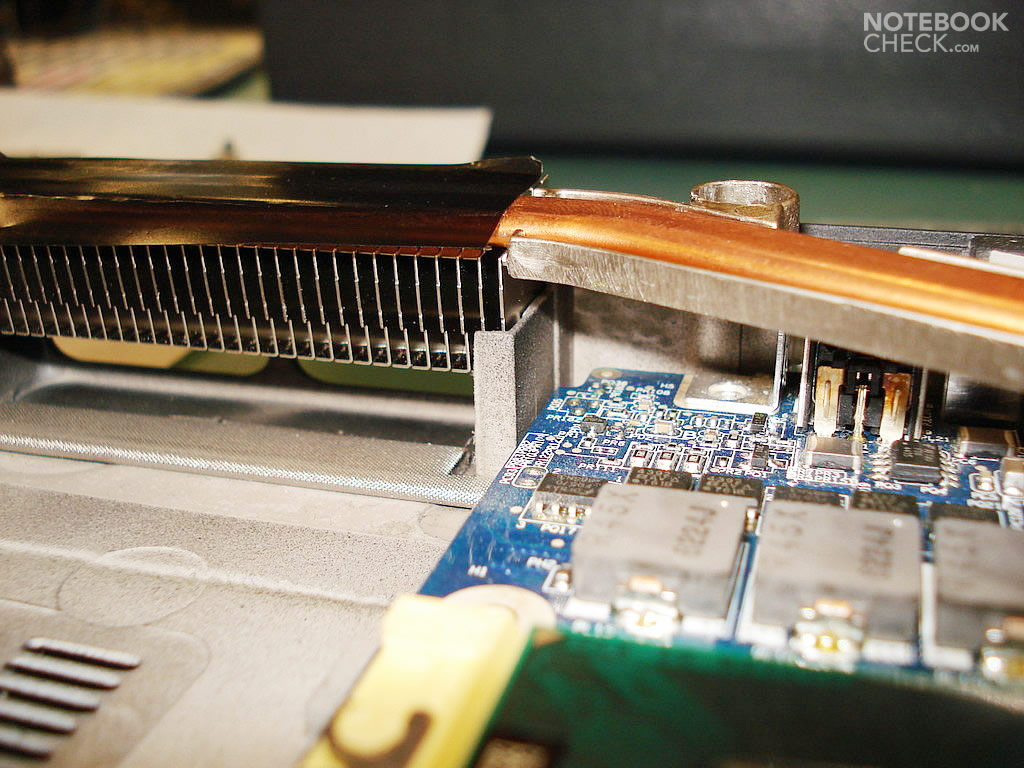
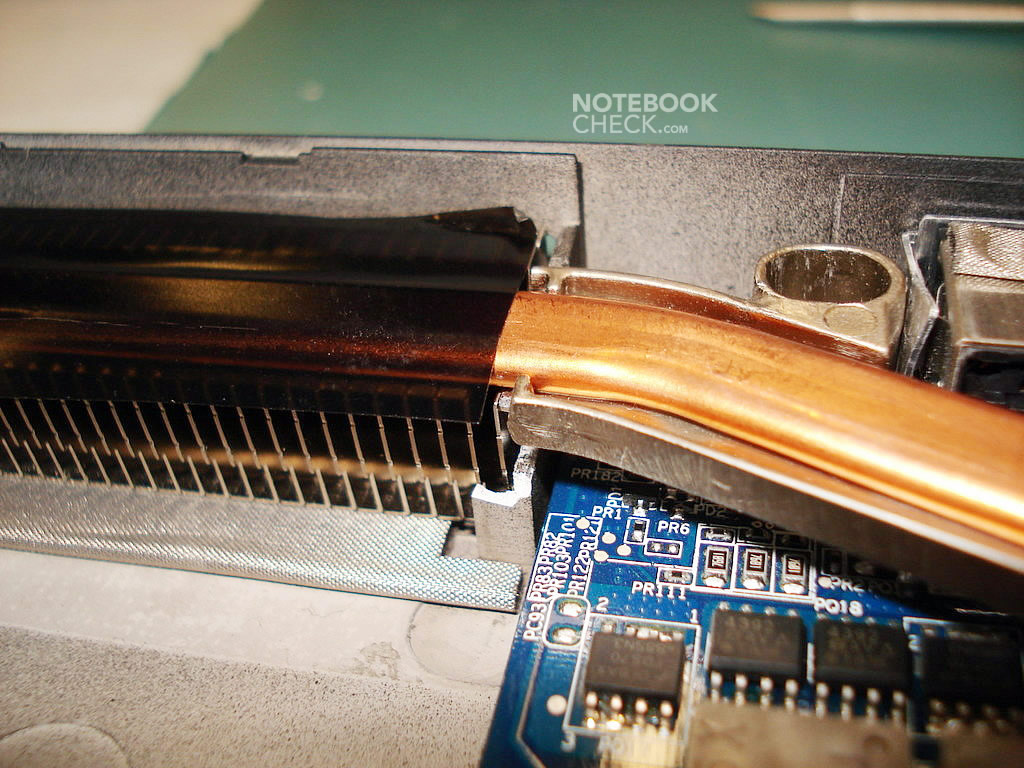
Now we are through to the motherboard and are almost ready to assemble a new GeForce Go 7900 GTX graphics card with dual heat pipe. The original GPU installed in my notebook was a GeForce Go 7800, which has only one heat pipe.
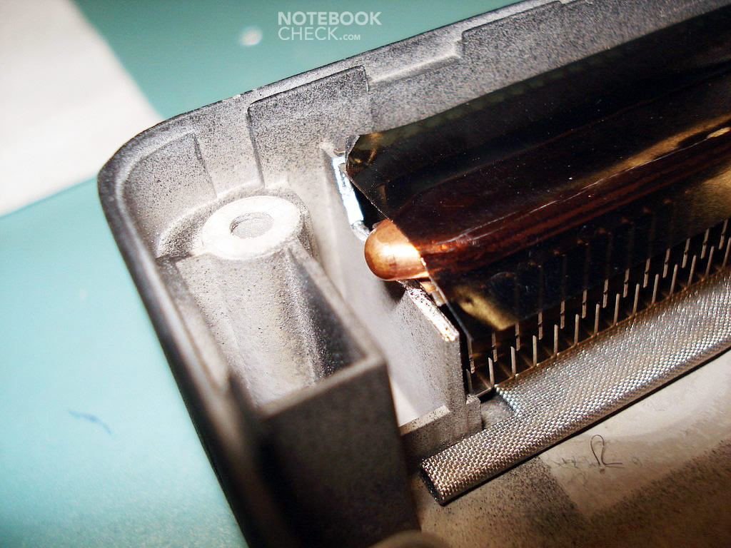
First, I had to check, if the left heat pipe (7900 GTX) would fit into the case. As you can see on the first picture, it doesn't seem to fit that well. So, a little modding is needed. For this purpose a pair of small pliers is needed in order to cut out two pieces of the case (from both sides). One thing is worth special consideration: the case of the notebook is very rigid, so, while cutting out undesired fragments, there are tiny splinters cropping up, which may get beneath the motherboard. Hence, one should blow those away with compressed air. Details on photos below.
After examining the result of our work, it's now time to place the brand new card into the slot. I orientated the video card on the arrangement of the screws affixing it to the printed circuit board (PCB), as it is very hard to arrange it using the PCI Express slot as a guide (it is nearly invisible during assembly).
Moving it gently, try to arrange the card ideally, screw counter-clockwise and press it to the motherboard. Be careful and mount the card horizontally and not aslant, as the slot is very damageable. You'll notice, when the card is in its place. Now, it's only a matter of screwing it in. See pictures below:
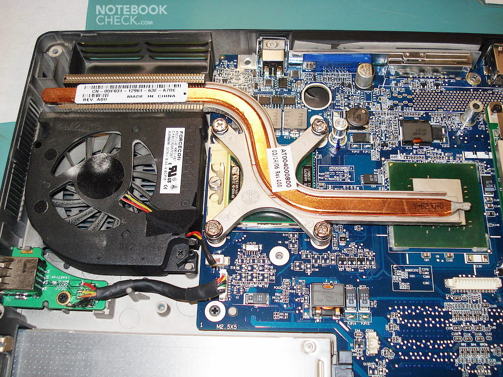
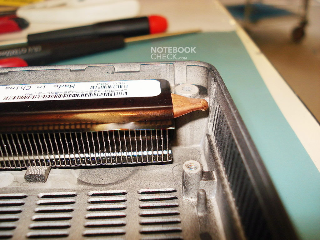
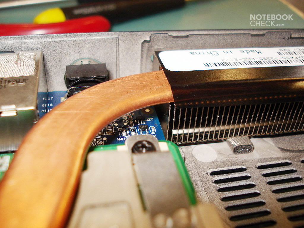
Fitting the left heat pipe:
There is plenty of room on the right side of the case. So, mounting this heat pipe will be trouble-free. Afterwards it looks like that:
After assembling the video card, it's time to install the cooler for both the CPU and the GPU. Appropriate steps have been described above, so I won't elaborate on them again.

It doesn't matter, if you affix the 7900 GTX's cooler first and then install the CPU's cooler, or other way round. They don't interfere with one another in any way.
After fixing all the parts of the cooling system, you are about to set up the top case and mount the display. First, you should place the top case on top of the base unit and affix it to the case with screws (red marks on the first photo). Leave the two upper openings empty - You'll finally need them for screwing the keyboard. Don't forget to reconnect the power switch, the touch pad, and the BIOS battery.
Affixing the LCD panel shouldn't pose any difficulty. You have to remember that you should drag the WLAN cables onto the other side of the case and connect them in a proper way (the white one - 1; the black one - 2) with the module. Then, you need to connect the LCD, pressing the connector slowly into the socket of the GPU, and place the cable into the recess of the case.
The connector of the power switch and the indicator lights, and the connector of the BIOS battery:
Finally, the keyboard including the power switch has to be put on the top cover. Please look above for details. If everything is done as it should, you can now turn the notebook on.
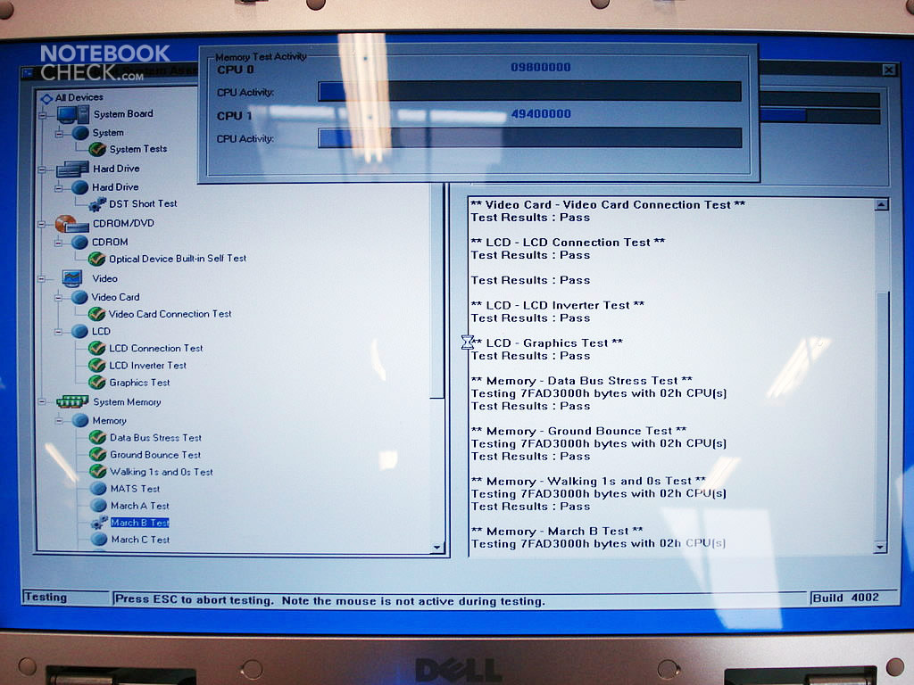
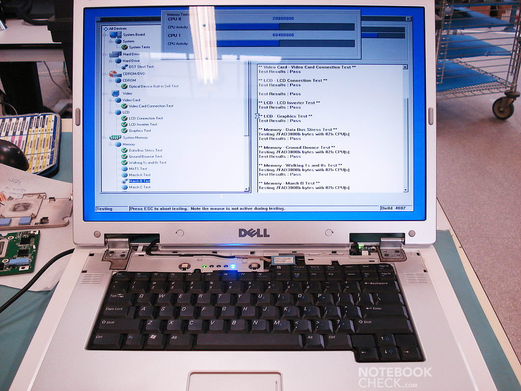
Press F5 immediately in order to run the diagnostic program, and, after performing the necessary tests, enter the BIOS, where you can see the following:
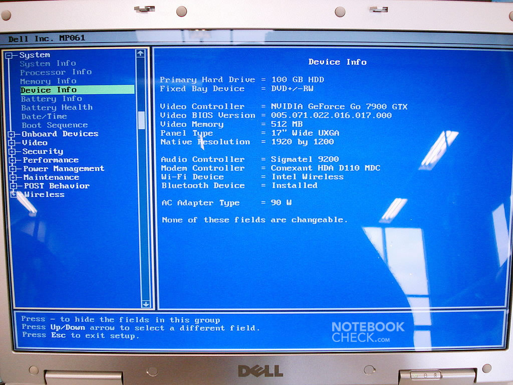
The provided GPU required the PA-10 90W power supply unit. The minimum for GF Go 7900 GTX 512MB and GF Go 7950 GTX 512MB GPUs is a PA-13 130W or a PA-15 150W power supply unit (PSU).
The standard clocks for the 7900 GTX card: 500MHz core; 1200MHz memory (GDDR3).
You can easily overclock it to 7950 GTX standards, which are 575MHz for the core, and 1400MHz for the memory. I don't recommend doing this with the 90W PA-10 PSU, though.
After installing the GPU and assembling the notebook, I suggest using modifiable drivers downloaded from this website:
http://www.tweaksrus.com/index.php?option=com_docman&task=cat_view&gid=163&Itemid=41/
After installing the MobileForce 97.92 M4 driver, I've got the possibility to change the clocks for both 2D and 3D graphics. Regardless of the driver, this is nothing extraordinary, but the possibility to downgrade the clocks for 2D mode to 15MHz for the core and 100MHz for the memory really surprised me. Possibly, these are just wrong slider settings, but in the case of the old GeForce Go 7800 card I managed to reduce the 2D clocks to 25MHz for the core and 400MHz for the memory.
As you might guess, it had quite an impact on the video cards temperature emissions, which varied between 50-60 degrees Celsius, with the fan turning on sporadically.
In the 3D mode, without operation characteristics (OC), the temperature of the 7900 GTX card reached 85 degrees Celsius. Possibly, replacing the thermal paste with an AC5 on the GPU would reduce the temperature by several degrees.
A big plus of the 7900 GTX GPU's cooling system is the dual heat pipe. It means that the card is being cooled in a twofold manner, and, so, doesn't heat so much. I confess, that I didn't manage to put the cooler off the GPU in order to apply some new thermal paste to the core. I failed to remove the radiator, as it was fixed too tightly. In the 7800 and the 7900 series the memory modules are placed on both sides of the printed circuit board (PCB). The bottom memory sticks are cooled by a thin sheet of metal.
Please refer to the following link for further details:
http://www.notebookcheck.net/Mobile-Graphics-Cards-Benchmark-List.844.0.html
Finally, I wish you good luck in disassembling the notebook and replacing some of its hardware.
Thanks to our partners of Notebookcheck Polen and Andi, who provided us with this case study.